Arturia Minilab 3 MIDI controller firmware #
This page should complement and expand on what I presented in this youtube video.
Obtaining update files #
Firmware images are included in the MIDI Control Center (MCC) software bundle, with obvious file names. Some of these like minilab-3_Firmware_Update_1.1.1.mnl3 are actually a zip archive which may contain multiple files for different hardware variants:
$ file MiniLab3_Firmware_Update_1_0_6.mnl3
MiniLab3_Firmware_Update_1_0_6.mnl3: Zip archive data, at least v2.0 to extract, compression method=store

$ binwalk MiniLab3_Firmware_Update_1_0_6.mnl3

DECIMAL       HEXADECIMAL     DESCRIPTION
--------------------------------------------------------------------------------
0             0x0             Zip archive data, at least v2.0 to extract, compressed size: 448, uncompressed size: 448, name: info.json
...

$ 7z l MiniLab3_Firmware_Update_1_0_6.mnl3

Type = zip
Physical Size = 371580

   Date      Time    Attr         Size   Compressed  Name
------------------- ----- ------------ ------------  ------------------------
2022-12-02 14:52:42 .....          448          448  info.json
2022-12-02 14:52:42 .....       198872       198872  MiniLab3_fw_1__fw1_0_6_835__2022_12_02.bin
2022-12-02 14:52:42 .....       171824       171824  MiniLab3_fw_2__fw1_0_6_455__2022_12_02.bin
------------------- ----- ------------ ------------  ------------------------
2022-12-02 14:52:42             371144       371144  3 files
The json file contains some interesting metadata:
    "version_number": "1.0.6",
    "date": "2022_12_02",
    "vendorid": "0x1C75",
    "method": "dfu",
    "images": [
        {
            "image_num": 0,
            "file_name": "MiniLab3_fw_1__fw1_0_6_835__2022_12_02.bin",
            "productid": "523"
        },
        {
            "image_num": 0,
            "file_name": "MiniLab3_fw_2__fw1_0_6_455__2022_12_02.bin",
            "productid": "8715"
        }
    ]
The vendorid and productid fields refer to USB VID:PID; MCC uses this to select the proper firmware file. It’s unclear why productid is in decimal while vendorid is hex…
Firmware format #
Cursory observation in a hex editor and binwalk -E indicate the firmware is raw and uncompressed. cpu_rec recognizes some ARM opcodes, as could be expected for this type of product.
Header and loading offset #
Here are the first 256 bytes of a typical file:
00000000: 75 1c 0b 02 00 00 98 08 03 00 f4 01 00 88 00 08  u...............
00000010: f7 ff 03 08 00 00 00 00 00 00 00 00 00 00 00 00  ................
00000020: 00 00 00 00 00 00 00 00 00 00 00 00 00 00 00 00  ................
00000030: 00 00 00 00 00 00 00 00 00 00 00 00 00 00 00 39  ...............9
00000040: 00 40 02 20 a5 ba 00 08 b9 b1 00 08 bb b1 00 08  .@. ............
00000050: 00 00 00 00 00 00 00 00 00 00 00 00 00 00 00 00  ................
00000060: 00 00 00 00 00 00 00 00 00 00 00 00 bd b1 00 08  ................
00000070: 00 00 00 00 00 00 00 00 bf b1 00 08 c1 b1 00 08  ................
00000080: f5 ba 00 08 f5 ba 00 08 f5 ba 00 08 f5 ba 00 08  ................
00000090: f5 ba 00 08 f5 ba 00 08 f5 ba 00 08 f5 ba 00 08  ................
000000a0: c9 b1 00 08 d9 b1 00 08 e1 b1 00 08 f9 b1 00 08  ................
000000b0: f5 ba 00 08 1d b2 00 08 f5 ba 00 08 2d b2 00 08  ............-...
000000c0: f5 ba 00 08 f5 ba 00 08 f5 ba 00 08 bd b2 00 08  ................
000000d0: cd b2 00 08 f5 ba 00 08 dd b2 00 08 f5 ba 00 08  ................
000000e0: f5 ba 00 08 f5 ba 00 08 f5 ba 00 08 f5 ba 00 08  ................
000000f0: f5 ba 00 08 ed b2 00 08 f5 ba 00 08 00 00 00 00  ................
Already some regularity is visible, but becomes more obvious if viewing as 32-bit, little-endian words:
00000000: 020b1c75 08980000 01f40003 08008800
00000010: 0803fff7 00000000 00000000 00000000
00000020: 00000000 00000000 00000000 00000000
00000030: 00000000 00000000 00000000 39000000
00000040: 20024000 0800baa5 0800b1b9 0800b1bb
00000050: 00000000 00000000 00000000 00000000
00000060: 00000000 00000000 00000000 0800b1bd
00000070: 00000000 00000000 0800b1bf 0800b1c1
00000080: 0800baf5 0800baf5 0800baf5 0800baf5
00000090: 0800baf5 0800baf5 0800baf5 0800baf5
000000a0: 0800b1c9 0800b1d9 0800b1e1 0800b1f9
000000b0: 0800baf5 0800b21d 0800baf5 0800b22d
000000c0: 0800baf5 0800baf5 0800baf5 0800b2bd
000000d0: 0800b2cd 0800baf5 0800b2dd 0800baf5
000000e0: 0800baf5 0800baf5 0800baf5 0800baf5
000000f0: 0800baf5 0800b2ed 0800baf5 00000000
From experience with working with stm32 devices, the last part looks like a list of pointers to flash (usually mapped at 0x0800 xxxx), and this would be a good place for a vector table. At this point I was not sure of the header length (if even present), so I made a few attempts at determining the memory load address. My method for this was to initially load the entire file at my best guess (0x0800 0000) in ghidra, and look at the disassembly and cross-references.
Example of wrong offset #
Near the beginning, here’s the list of suspected pointers:
        08000078 bf b1 00 08     addr       DAT_0800b1bf
        0800007c c1 b1 00 08     addr       DAT_0800b1c1
        08000080 f5 ba 00 08     addr       LAB_0800baf4+1
        08000084 f5 ba 00 08     addr       LAB_0800baf4+1
        08000088 f5 ba 00 08     addr       LAB_0800baf4+1
Not much to see here, these point to odd addresses which is typical of cortex ARM cores (the LSbit being 1 indicates Thumb mode). The code at those locations doesn’t reveal much either way, but they don’t really look like interrupt handlers, for example:
                             LAB_0800b1d8+1
        0800b1d8 18 48           ldr        r0,[DAT_0800b23c]
        0800b1da fb f7 cd fa     bl         FUN_08006778
        0800b1de 43 b2           sxtb       r3,r0
Modifying a register right after entry is… unusual (typical interrupt handlers would save registers on stack before modifying them). Another thing I like to look at is references to strings:
        08028fab                 ds         "Arturia"
        08028fb3                 ds         "Firmware Updater"
        08028fc4                 ds         "Minilab3 MIDI"
                             s_RU_08028fe1                                   XREF[0,1]:   0802e7ec(*)
        08028fd2                 ds         "Minilab3 DIN THRU"
let’s look at the source of this reference at 802e7ec:
0802e7ec addr s_RU_08028fd2+15 = "RU"
more confirmation that the loading offset is wrong: almost no string references, and this one points in the middle of the string. Unlikely.
Memory map clues #
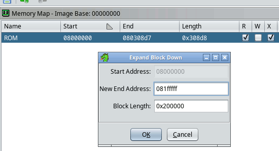
To gather more clues, I then extend the memory range by a large number so that any absolute reference that falls outside the defined bytes will still show up in ghidra.

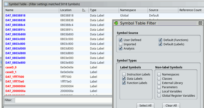
Analysis must be run again. Enabling the “aggressive instruction finder” option (AIF) is helpful to maximize code coverage; it doesn’t matter if it wrongly marks a lot of data as code (it often does) because these are still early guesses and I will be keeping none of these results. Then we can use the Symbol Table view:
 Working backwards, I first examine cross-references to the handful of vaguely similar pointers:
        0802fed2 00              ??         00h
        0802fed3 20              ??         20h
        0802fed4 00 e0 03 08     addr       DAT_0803e000
        0802fed8 00 d8 03 08     addr       DAT_0803d800
        0802fedc 00 d0 03 08     addr       DAT_0803d000
        0802fee0 00 c8 03 08     addr       DAT_0803c800
        0802fee4 00 c0 03 08     addr       DAT_0803c000
        0802fee8 00              ??         00h
        0802fee9 00              ??         00h
No help here, none of the code appears to be using these. Next, references to DAT_0803891c lead to this very interesting function:
FUN_08002bdc();
for (iVar2 = 0; &DAT_20000004 + iVar2 < &DAT_20000780; iVar2 = iVar2 + 4) {
  *(undefined4 *)(&DAT_20000004 + iVar2) = *(undefined4 *)((int)&DAT_0803891c + iVar2);
}
for (puVar1 = (undefined4 *)&DAT_20000780; puVar1 < (undefined4 *)0x20005e9c; puVar1 = puVar1 + 1)
{
  *puVar1 = 0;
}
This definitely follows a very common pattern:
- copying a block of initialized data from flash to ram (.idata section)
- clearing another block of ram (.bss section)
Going by this assumption, the block of data starting at 803 891c must map into the firmware image. The first for loop copies 0x20000780-0x2000 0004=0x77c bytes; this implies the firmware should extend to 0x803 891c + 77c = 0x803 9098. Since the file size is 0x308d8, we are missing 0x87c0 bytes at the end. Thus the new load address should be 0x800 87c0. Maybe an illustration is in order:
 --initial map guess

                      abs refs to 0x803891C etc.
                      ^          :   :  :
                      |          :   :  :     / /
        ---+----------------+----v---v--v----/ /-+------------+--
           |<.bin contents >|  ?  ?   ?     / /  |     RAM?   |
       ----+----------------+--------------/ /---+------------+--
           |                              / /    |
           |                                     |
         0x800 0000                            0x2000 0000
         "start of flash"

********** ********* ********* ********* ********* ********
 --second attempt
                        last 'good' xref..
                             (0x8039098) :
                                         :    / /
        ---+------------+----------------v---/ /-+------------+--
           |            |<.bin contents >|  / /  |     RAM?   |
         --+------------+----------------+-/ /---+------------+---
           |                              / /    |
           |                                     |
           0x800 0000                          0x2000 0000
           "start of flash"
Second (third) attempt #
Going through the same steps with a clean slate, and going back to same strings, we end up with much better disassembly and clean decompilation:
  switch(param_3) {
  case 6:
    pcVar1 = "Firmware Updater";
    break;
  case 7:
  case 8:
    pcVar1 = "Minilab3 MIDI";
    break;
  case 9:
  case 10:
    pcVar1 = "Minilab3 DIN THRU";
    break;
  case 0xb:
  case 0xc:
Examining many other areas and cross references confirm this as the most likely mapping and we can proceed with annotation and analysis. Note that many of these steps, would have been omitted if I had known earlier that the processor is indeed an stm32g0b0ret6.
Header contents #
Looking at the header during the process, a few things became obvious. Here are again the first few bytes of the file:
00000000: 75 1c 0b 02 00 00 98 08 03 00 f4 01 00 88 00 08  u...............
00000010: f7 ff 03 08 00 00 00 00 00 00 00 00 00 00 00 00  ................
00000020: 00 00 00 00 00 00 00 00 00 00 00 00 00 00 00 00  ................
00000030: 00 00 00 00 00 00 00 00 00 00 00 00 00 00 00 39  ...............9
00000040: 00 40 02 20 a5 ba 00 08 b9 b1 00 08 bb b1 00 08  .@. ............
00000050: 00 00 00 00 00 00 00 00 00 00 00 00 00 00 00 00  ................
00000060: 00 00 00 00 00 00 00 00 00 00 00 00 bd b1 00 08  ................
00000070: 00 00 00 00 00 00 00 00 bf b1 00 08 c1 b1 00 08  ................
00000080: f5 ba 00 08 f5 ba 00 08 f5 ba 00 08 f5 ba 00 08  ................
- 1c75 the usb VID
- 020b must be the usb PID
- ‘98 08 03 00’ looks a lot like 0x30898 in little endian ordering, and is also very close to the file size (0x308d8) minus 0x40
- ‘f4 01’: unknown
- ‘00 88 00 08’ -> 0x800 8800, suspiciously close to our guessed address 0x800 87c0, with a delta of 0x40…
- ‘f7 ff 03 08’ -> 0x803 fff7, unclear
- bunch of 00 padding
- ‘39’ unclear, possibly part of a checksum for the firmware file?
- Starting at 0x40 something that matches perfectly the entries of a vector table for the stm32g0
My conclusion then, is that the first 0x40 bytes are a header that is probably not written to flash at all. So something like this:
struct header {
	u16 usb_VID;	// JSON "vendorid"
	u16 usb_PID;	// JSON "productid"
	u16 unk_04;	// always 0000 ?
	u32 fw_size;	// un-aligned u32 ! = firmware.bin filesize - 0x3F
	u16 offs_0a;	//?
	u32 load_addr;	// 0x0800 8800
	u32 unk_addr_10;	// 0x0803 fff7 = ?
	.... padding
	u8 pad_3C[3]
	u8 lastbyte;	//checksum for hdr ?
} __packed