Intro #
This flash strobe (and similar models VS-202, VS-302, etc) was made some time around 1984 by “Crown Pro Lighting”, an obscure and now defunct brand. There is a very little information about these online.
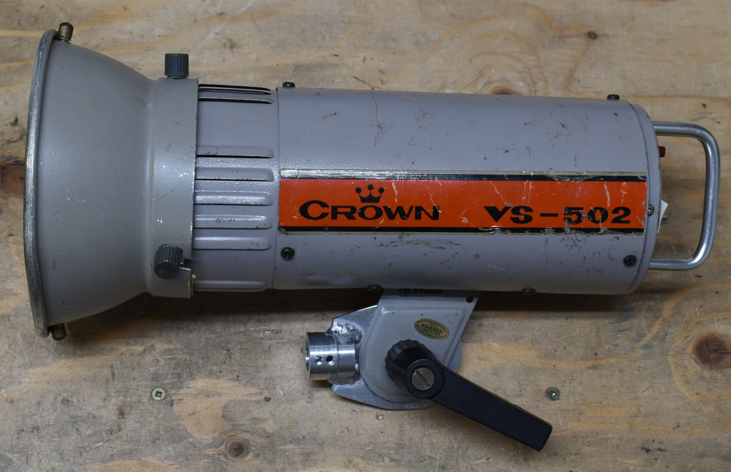
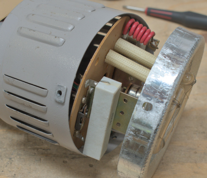
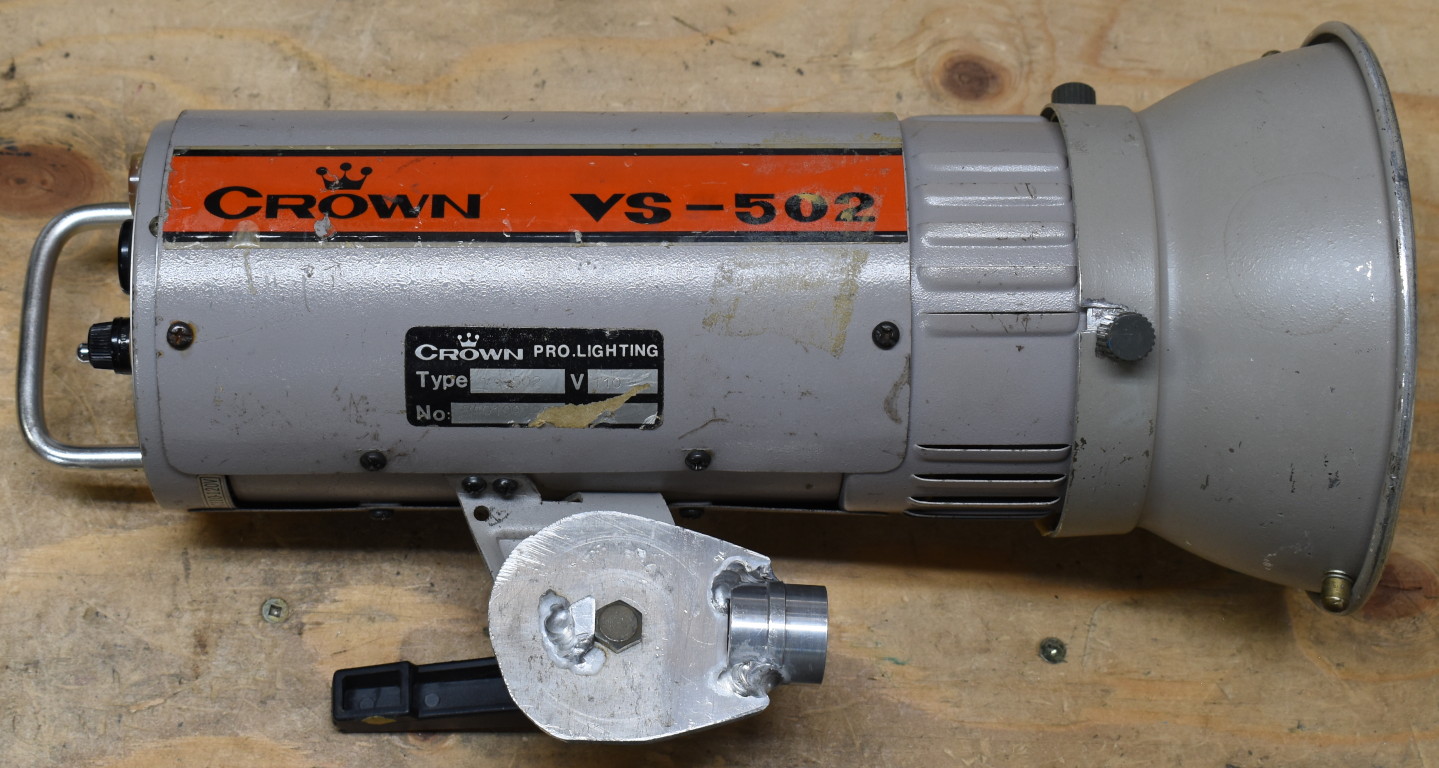 Mine was missing a mounting bracket; a few scraps of aluminum did the trick.
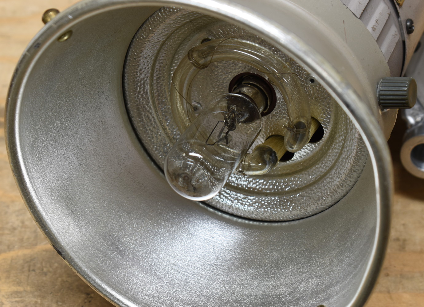 The modeling light is a type CDD ;120V 100W T8 bayonet.
Controls #
Fairly self explanatory. The left switch controls the flash section independently of the modeling light. The power level switch controls both.
There is an optical sensor (facing back) for basic slave operation.
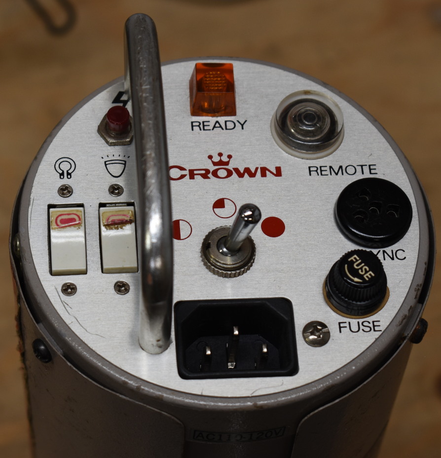
Sync connector #
The 4-pin sync connector is a bit of an oddball; made by EDK Japan, and also found on Lafayette HB-525 CB radios of the late ’70s. Sometimes these connectors can be found on epay with the following keywords:
- “vintage 4-pin Y microphone plug”
- Lafayette 99-62648
- Philmore P604C
- Vanco CBC-4Y
Sync voltage is fairly high as expected, around 242V.
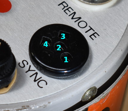
Pinout (numbering is molded on the back of the connector):
- AUX_TRIG
- x
- TRIG+
- TRIG-
Typical trigger would short pins 3 and 4. Caution! Neither of these is at ground potential, and should probably not be connected to any sane(r) equipment. AUX_TRIG: unclear purpose, could be positive-edge input; also not at ground potential. 12:1 divider into SCR gate with delay, see schematics.
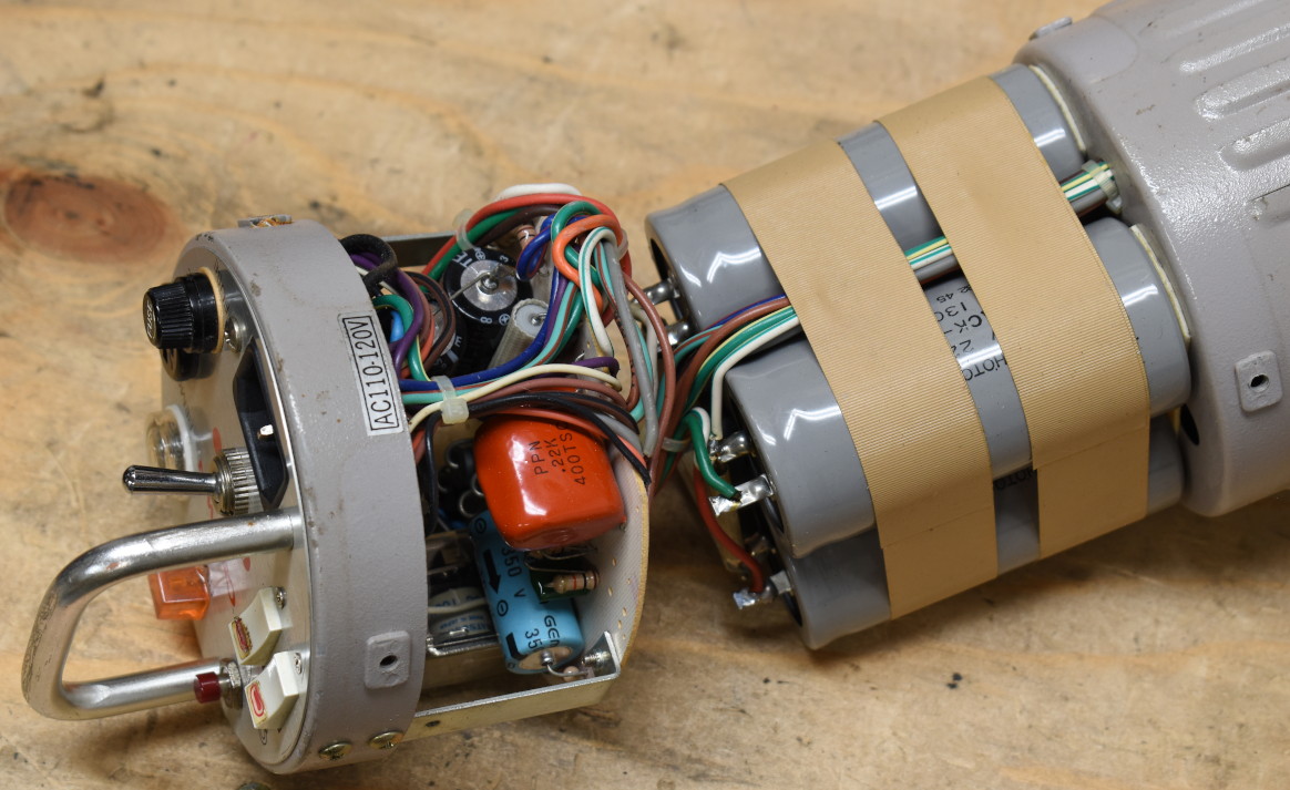
Disassembly #
To state the obvious: HIGH VOLTAGE inside! Don’t open if you don’t know what you’re doing. To discharge most of the energy:
- set power level to maximum (only way to discharge all capacitor banks)
- disconnect from AC
- push the test button to fire the flash
- ideally leave it alone for a few hours or overnight, assuming the built-in discharge resistors work
Even after popping the flash, caps are still at least 50-80V which must be treated with respect. Unfortunately there is no easy way to discharge the capacitors from the outside and the flash tube contacts are not accessible.
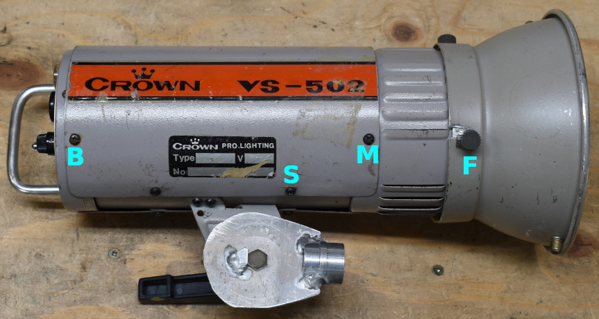
Back panel #
Remove modeling bulb, stand up the flash on its reflector, remove 3 black screws marked ‘B’. Full capacitor voltage is present on many of the wires.
Front module #
Remove three thumb screws ‘F’ and reflector, front module should slide out. High voltage also very much present here.
Middle section #
Only really necessary to get to the capacitor bank. Screws ‘M’; the ‘S’ screws only hold the mounting bracket and can probably stay there.
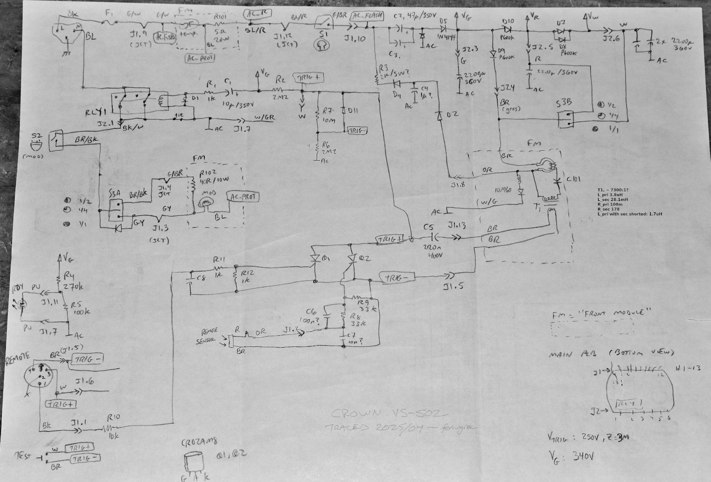
Schematics #
Should be mostly correct, albeit hard to read.