The 4195A is an old network + spectrum analyzer. I’ve repaired mine a few years ago.
Floppy disk conversion #
There was (luckily) nothing wrong with my drive, but they don’t last forever. Also disks are unreliable and getting hard to find. In the 4195A, disks can be used to save:
- instrument state and settings (incidentally, when a GPIB controller asserts IFC, the 4195 reverts to default state… super annoying)
- program point table (i.e. list of frequencies or bias points that may have been painstakingly entered…)
- register data (e.g. A, B trace data, etc)
- user programs
gotek, flashfloppy #
I chose to replace the entire drive with a gotek-type emulator, and use Keir Fraser’s excellent FlashFloppy. There’s nothing really special about the hardware, and it comes in multiple variants of housing size, display options, and mcu. There are advantages to using the newer boards based on an AT32F435 (more RAM, more speed, more better), but that kind of detail is hard to eke out from online listings sometimes, and aliexpress’s search engine is absolutely horrendous in showing what it thinks you want, regardless of the keywords you put in. Anyway, I ended up with the slighty-less good AT32F415.
Note ! #
These emulators work at a very low level below individual bits (!), and have no notion of filesytems. They only stream / write a raw representation of the disk surface. You can save / copy this raw image but it is not easy to interact with at a file level. Not even sure if possible at all for LIF disks like this. This means you can’t just hop the USB drive over to a computer and extract files.
Original drive #
The original is a bit of an oddball, typical of the 80’s… it’s a Sony MP-F52W drive with an odd height, and more importantly, an odd 34-pin connector pinout. First, the numbering doesn’t match the ‘modern’ 34-pin IBM standard, and also carries +5 and +12V power. A direct connection is impossible. On top of that, it has unusual specs of RPM and low-level formatting. (600 RPM, 77 or 80 sectors depending who you ask, 256B/sector, total 616k or 630kB capacity)
Luckily this drive is fairly common accross HP machines of the time, and I found most of the info I needed in two github tickets, https://github.com/keirf/flashfloppy/discussions/870 and https://github.com/keirf/flashfloppy/discussions/683 .
Details #
Somehow it still took hours to figure out all the finer points, and minor differences to the particular devices discussed in the tickets mentioned above.
- my gotek board needed a jumper at the “MO” position to connect the
MOTOR_ONsignal - wired one signal to PA14 which is available on one of the unpopulated headers; unclear if it’s actually necessary at all
- unable to format a blank image, most likely because the F415 runs out of RAM (this is why the F435 is nicer)
- due to above, I was unable to use images created by
mk_hfe.pyincluded in FlashFloppy - HxC, an entirely different yet equally excellent solution, provides software that can create pre-formatted LIF images. This worked.
- note, flashfloppy works at such a low level, that the raw image file cannot easily be parsed or edited as a filesystem. Thus, I treat this as a ‘hard drive’ for the 4195, not as a way to exchange files between machines.
FlashFloppy files #
Here is my current FlashFloppy config and blank hfe image
Adapter wiring #
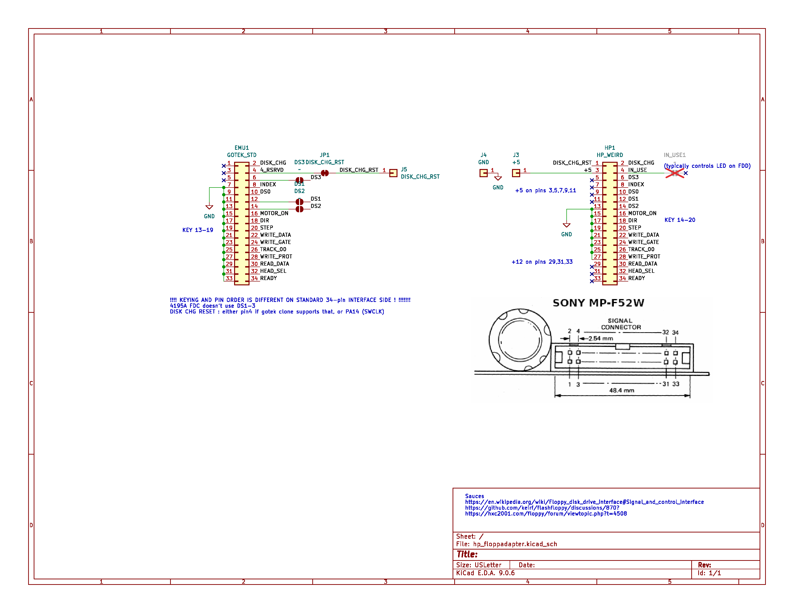
Adapter PCB #
I built a small adapter PCB, fabbed with OSHpark, and can be re-ordered here. (To be clear, I’m not selling these nor gaining anything by that; the link is just a convenience to re-use the files I uploaded)
My first iteration had been a partial failure, as the stock ribbon cable isn’t quite long enough , and not aligned with the gotek connector. This Rev2 fixes that nicely, and will probably work in many HP instruments with this same Sony drive.
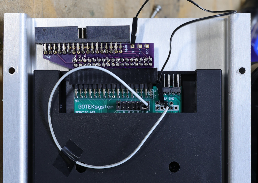
Note the two flying wires :
- +5V from adapter PCB to gotek.
- DISK_CHANGE_RESET to PA14 (SWCLK)
You can download the KiCad design files.
Connectors are simple through-hole, right-angle 34-pin connectors; preferably shrouded and/or keyed. Double-check orientation and fitment before ordering and assembling !
GPIB hardcopy #
A few challenges : the 4195A predates SCPI, and only produces HPGL (and possibly monochrome PCL) for exporting screenshots. I have used KE5FX’s 7470 Plotter Emulator software, but with mixed results partially due to running it inside a VM, with questionable USB-GPIB hardware. Also, there were some rendering issues due to the ordering in the HPGL data itself : the graticule is rendered after the traces !
I have a standalone utility to help with that: https://github.com/fenugrec/hpgl_reorder
To automate getting the screenshots, I made a python script that lets me enter a plot title, and runs hp2xx to convert to a more usable PNG file. Script available in my hp4195a_utils git repo
Probe power connector #
As with countless HP (and even other manufacturer’s) equipment, the 4195 provides external power for active probes and such. They use a proprietary connector that is simply not available. There are at least two alternatives :
- gut a standard D-subminiature, and cut / file to the proper shape. Pin diameter and spacing are “close enough”. No photos, it’s ugly.
- Binder 09 9748 70 03 : untested, also needs a bit of shaping with a file to fit the D-shaped socket.
Extracting a bitmap font #
It started with the assumption that this machine would use a bitmap font; the alternative (a vector font) much less likely for such an instrument of the late 80’s.
Examining the schematics, the display board uses a NEC uPD7220 display controller (GDC). It is quite capable of drawing “hardware-accelerated” lines and curves, but it also has provisions for drawing plain bit-mapped characters.
The 4195 is a complex machine with a two processor boards (A6 and A8) each with their onboard CPU, ROM, and RAM, as well as a shared RAM bank. The service manual indicated that the A6 board is most likely the one driving the graphics interface.
The CPU on this board is an MC68000, with 24 bits of external address space and a 16 bit data bus. The ROM ICs are wired as two banks (upper + lower bytes). The mapping turned out to be a simple linear layout, but the schematics were missing some annotations and the chip-select logic was confusing to say the least. After a few iterations of combining ROM dumps, loading in Ghidra, and looking at disassembly, I have deduced the following memory map:
- program ROM at 0 (704 kB); all ROM “pages” are contiguous
- shared RAM at 0x40 0000
- backup RAM at 0x80 0000
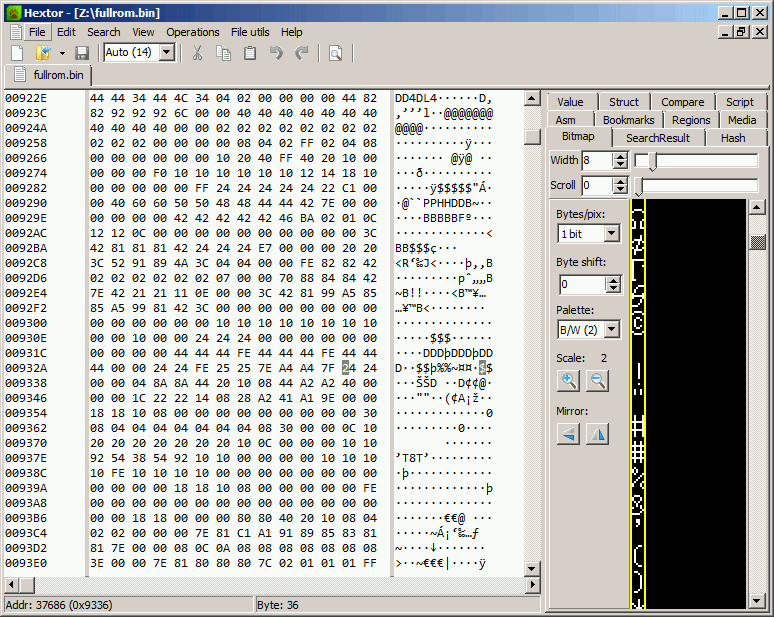
Then, I spent some time defining areas of code near anything that looked like a printable string. This led me to a function that had all the characteristics I would expect for drawing characters. This involves writing a few commands/parameters into GDC registers at 0xf801c1/f80133, followed by 8+5 consecutive writes, taken from a large array in ROM :
pcVar10 = (char *)boot_err_stringtbl[errcode];
char_cnt = 0x2b;
do {
	do {
		/* range check on ASCII special chars < 0x20 */
	  bVar6 = (*pcVar10 & 0x7fU) - 0x20;
	  if ((char)bVar6 < '\0') {
		p_bitmap = &charbit_space;
	  }
	  else {
		p_bitmap = (&font_tbl)[bVar6];
	  }
...
		// set cursor position
	  DAT_00f801c3 = CURS;
	  puVar9 = puVar8 + 1;
	  DAT_00f801c1 = *puVar8;
	  DAT_00f801c1 = 0x3c;
	  puVar8 = puVar8 + 2;
	  DAT_00f801c1 = *puVar9;

	  DAT_00f801c3 = 0x78;
			/* 0x78 : subsequent writes go into &PRAM[8] == &GCHR[] */
	  DAT_00f801c1 = *p_bitmap;
	  DAT_00f801c1 = p_bitmap[1];
	  DAT_00f801c1 = p_bitmap[2];
	  DAT_00f801c1 = p_bitmap[3];
	  DAT_00f801c1 = p_bitmap[4];
	  DAT_00f801c1 = p_bitmap[5];
	  DAT_00f801c1 = p_bitmap[6];
	  DAT_00f801c1 = p_bitmap[7];
...
Initially I had tried simply viewing the entire ROM as a monochrome image, hoping to visually recognize patterns and avoid needing to work on disassembly, but the tools I tried for this were not well adapted and I quickly abandoned this approach. However, knowing exactly where to look, the bit patterns now emerged clearly:
It was then a simple matter of writing a quick tool to remap and extract the entire font. srecord and monobit helped with the final steps.
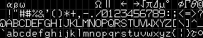
The final fontier #
This is a render of the entire font, implementing characters 0x00-0x7F with a few blank fillers:
Not sure where else to post this, so I at least submitted the font as a ‘YAFF’ file on Rob Hageman’s hoard-of-bitfonts repo.
Also available here.